 English
 Español
  Português
  русский
  Français
  日本語
日本語  Deutsch
  tiếng Việt
  Italiano
  Nederlands
  ภาษาไทย
  Polski
  한국어
한국어  Svenska
  magyar
  Malay
Malay  বাংলা ভাষার
  Dansk
Dansk  Suomi
Suomi  हिन्दी
  Pilipino
  Türkçe
  Gaeilge
  العربية
  Indonesia
  Norsk
Norsk  تمل
تمل  český
český  ελληνικά
  український
  Javanese
  فارسی
فارسی  தமிழ்
தமிழ்  తెలుగు
  नेपाली
  Burmese
  български
  ລາວ
ລາວ  Latine
  Қазақша
  Euskal
  Azərbaycan
  Slovenský jazyk
  Македонски
  Lietuvos
  Eesti Keel
  Română
  Slovenski
  मराठी
मराठी  Srpski језик


Henan Shuangxin: How to conduct 3C fire damper test?
2022-11-25
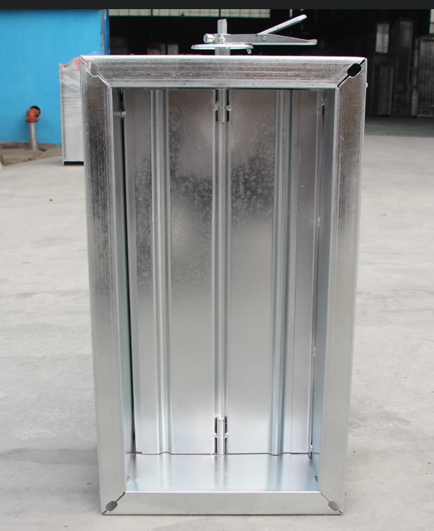
In accordance with the national standard Fire Dampers for Building Ventilation and Smoke Extraction Systems GB15930-2007, fire 3C fire dampers need to test 12 items of the product, including "appearance, tolerance, driving torque, reset function, temperature sensor control, manual control, electric control, insulation performance, reliability, corrosion resistance, air leakage at ambient temperature, and fire resistance". Henan Shuangxin fire damper manufacturer will give you detailed explanations.
1. Basic requirements for fire damper product test:
a. The structure, materials and parts of the test piece shall be consistent with the actual use.
b. The test shall be carried out on a clean test piece, and it is not allowed to replace parts during the test.
2. Test items of fire damper products
a. Appearance
The appearance quality of the valve shall be inspected by the method of "visual inspection and hand touch".
3. Tolerances
The linear dimension tolerance of the valve shall be measured with a steel tape. The accuracy of the steel tape is ± 1mm.
4. Driving torque
4.1 Test equipment
Spring dynamometers or other dynamometers, with accuracy of 2.5; The accuracy of steel tape or ruler is ± 1mm.
4.2 Test steps
a. After the fire damper or smoke exhaust fire damper is fixed according to the service state, remove the heavy hammer, spring, motor or pneumatic parts that generate the closing force. Use a dynamometer to move the main blade shaft of the blade from the fully open state to the closed state, read the maximum tension required on the main blade shaft when the blade is closed, measure the output arm, and calculate the maximum torque. Torque calculation formula: M = F · h
Where: M -- torque, in Newton meters (N · m);
F - tension, in newton (N);
H - force arm, unit: m.
b. Measure and calculate the driving torque actually applied to the main blade shaft of the fire damper by the weight, spring, motor or pneumatic parts. The driving torque is calculated according to the formula (M=F · h).
c. Calculate the ratio between the driving torque and the required torque of the main blade shaft of the fire damper.
5. Reset function
Input the electric control signal or manually operate the reset mechanism of the valve, and visually inspect the reset condition of the valve.
6. Temperature sensor control
6.1 Test equipment
Water bath or oil bath with heater and agitator and necessary measurement and control instruments. The accuracy of the instrument for measuring water temperature is ± 0.5 ℃. The accuracy of the instrument for measuring oil temperature is ± 2 ℃.
6.2 Test steps
a. Adjust and control the heater to heat the water in the water bath. At the same time, open the agitator. When the water temperature reaches 65 ℃± 5 ℃ and keeps constant temperature, completely immerse the temperature sensor end of the temperature sensor in water for 5min, and observe the action of the temperature sensor.
b. Take out the temperature sensor and cool it naturally to normal temperature. The regulating heater will continue to heat the water in the water bath. When the water temperature reaches 73 ℃± 0.5 ℃ and the constant temperature is maintained, completely immerse the end of the temperature sensing element of the temperature sensor into the water for 1mm, and observe the action of the temperature sensor.
7. Manual control
7.1 Test equipment
The accuracy of spring dynamometer or other dynamometer shall be 2.5.
7.2 Test steps
7.2.1 Make the valve fully open or closed, connect the dynamometer with the manually operated handle, pull rope or button, and apply the force to it through the dynamometer to close or open the valve. The measured force is the manual closing or opening operating force.
8. Electric control
8.1 Blade position output signal
Make the valve closed or open, connect the reset circuit in the actuator, the valve shall be opened or closed, and use a multimeter to measure the output signal of the position of the valve blade.
8.2 Rated current and rated voltage
The rated working voltage and rated working current of the electric control circuit in the valve actuator shall be measured with a voltmeter and ammeter whose accuracy is not less than 0.5 and whose range is not more than twice the actual measured value.
8.3 Withstand voltage fluctuation
8.3.1 Test equipment: DC stabilized power supply. The maximum output voltage is 30V.
8.3.2 Test steps:
a. Make the valve fully open or closed, connect the DC stabilized voltage power supply to the electric control circuit in the actuator, adjust the output voltage of the DC stabilized voltage power supply to make it 15% lower than the rated working voltage of the valve, connect the control circuit, and the valve shall close or open.
b. Disconnect the control circuit, fully open or close the valve, adjust the output voltage of the DC stabilized voltage power supply to make it 10% higher than the rated working voltage of the valve, connect the control circuit, and the valve shall close or open.
9. Insulation performance
The electrical insulation resistance of valves shall be measured according to 5.8.3 in GB 4717-1993, and the test equipment shall comply with 5.8.4 in GB 4717-1993.
10. Reliability: Closing reliability
Open the fire damper and start the actuator to close it. Repeat the operation for 50 times.
When the fire damper has several different control modes at the same time, 50 times of operation shall be evenly distributed. The fire damper with regulating function shall be tested at the maximum and minimum opening positions respectively, and the number of operations shall be evenly distributed.
Note: For temperature sensor control mode, simulation test can be conducted according to the working principle of temperature sensor control.
11. Corrosion resistance
11.1 Test equipment: salt spray box or salt spray chamber.
The materials in the salt spray box (chamber) shall not affect the corrosion performance of salt spray; Salt mist shall not be directly sprayed on the valve; The condensed brine at the top of the tank (chamber) shall not drop on the valve; The brine flowing from the four walls shall not be reused.
The salt spray box (room) shall be equipped with air conditioning equipment to control the air temperature in the salt spray box (room) within the range of 35 ℃± 2 ℃ and maintain the relative humidity greater than 95%.
The brine solution consists of chemically pure sodium chloride and distilled water, with a mass concentration of (5 ± 0.1)% and a pH value of 6.5~7.2. The amount of fog reduction shall be controlled between 1mL/(h · 80cm2) and 2mL/(h · 80cm2).
11.2 Accuracy of measuring instruments
Temperature: ± 0.5 ℃;
Humidity: ± 2%.
11.3 Test steps
11.3.1 Before the test, all grease on the valve surface shall be cleaned with detergent. Install the valve in the salt spray box (chamber). The opening shall be upward, and the axis of each blade of the valve shall form an angle of 15 °~30 ° with the horizontal plane.
11.3.2 During the test, the valve is in the open state. Take 24h as a cycle, spray continuously for 8h, and then stop for 16h. A total of 5 cycles are tested.
11.3.3 During spraying, the temperature in the salt spray box (room) shall be kept at 35 ℃± 2 ℃ and the relative humidity shall be greater than 95%; When stopping spraying, do not heat, close the salt spray box (chamber), and cool naturally.
11.3.4 After the test, take out the valve, dry it at room temperature for 24h, and then conduct the opening and closing test on the valve.
12. Air leakage at ambient temperature
12.1 Test equipment
12.1.1 Basic equipment: including gas flow measurement system and pressure measurement and control system.
12.1.2 Gas flow measurement system
It is composed of connecting pipe, gas flowmeter and induced draft fan system.
a. Connecting pipe: the valve is connected to the gas flowmeter through the connecting pipe. The connecting pipes shall be made of steel plates not less than 1.5mm thick. For rectangular valves, the width and height of the pipe opening corresponds to the outlet size of the valve, and the length of the pipe is twice the diagonal of the opening, with a maximum length of 2m. For round valves, the diameter of the pipe opening corresponds to the outlet size of the valve, and the length of the pipe is twice the opening diameter, with a maximum length of 2m.
b. Gas flowmeter: standard orifice plate should be used. The processing, fabrication and installation of orifice plates shall comply with the provisions of GB/T 2624. A gas flow regulator shall be fitted at the front end of the measuring pipe.
C. Induced draft fan system: including induced draft fan, inlet valve, regulating valve, and flexible pipe connecting gas flowmeter and induced draft fan.
12.1.3 Pressure measurement and control system
The pressure before and after the valve is measured by a pressure sensor. The pressure outlet shall be on the center line of the side of the connecting pipe, and the distance from the valve shall be 0.75 times of the pipe length. The static pressure difference before and after the valve is regulated and controlled by the inlet valve and the regulating valve.
12.2 Accuracy of measuring instruments
Temperature: ± 2.5 ℃;
Pressure: ± 3Pa;
Flow: ± 2.5%.
12.3 Test steps
12.3.1 Install the valve on the pipeline of the test system and keep it closed. The inlet is sealed with a non leakage plate. Start the induced draft fan, adjust the inlet valve and regulating valve, and make the static pressure difference of air before and after the valve 300Pa ± 15Pa or 1000Pa ± 15Pa. After 60s of stabilization, measure and record the differential pressure on both sides of the orifice plate, the gas pressure in front of the orifice plate and the gas temperature in the pipe after the orifice plate. At the same time, measure and record the atmospheric pressure during the test, and calculate the gas flow in this state according to the calculation formula in GB/T 2624. The air leakage rate of the system shall be measured once every 1min and continuously for 3 times, and the average value shall be taken as the air leakage rate of the system. If the air leakage of the system is greater than 25m3/h, the sealing of each connection shall be adjusted until the air leakage of the system is not greater than 25m3/h.
12.3.2 Remove the sealing plate at the inlet of the valve, and the valve is still closed. Adjust the inlet valve and regulating valve to keep the static pressure difference between the front and back of the valve at 300Pa ± 15Pa or 1000Pa ± 15Pa. After 60s of stabilization, measure and record the differential pressure on both sides of the orifice, the gas pressure in front of the orifice and the gas temperature in the pipeline after the orifice. At the same time, measure and record the atmospheric pressure during the test. Calculate the gas flow in this state according to the calculation formula in GB/T 2624.
Note: The static pressure difference of gas selected for fire damper and smoke exhaust fire damper is 300Pa ± 15Pa, and the static pressure difference of gas selected for smoke exhaust damper is 1000Pa ± 15Pa.
12.3.3 Calculation of valve air leakage under ambient temperature.
13. Fire resistance
1. Test equipment
1.1 Basic equipment
It includes four parts: fire resistance test furnace, air array flow measurement system, temperature measurement system and pressure measurement and control system. There is a section of connecting pipe made of steel plate with thickness not less than 1.5mm between the test furnace and the valve. Its opening size corresponds to the inlet size of the valve, and the length is greater than 0.3m.
1.2 Fire resistance test furnace
The fire resistance test furnace shall meet the temperature rise conditions specified in 5.1 and pressure conditions specified in 5.2 of GB/T 9978-1999.
1.3 Gas flow measurement system: the gas flow measurement system is the same as 7.12.1.2.
1.4 Temperature measurement system
The temperature in the furnace (the temperature of the fire facing surface of the test piece) is measured with a thermocouple with a wire diameter of 0.75 mm~1.00 mm. The length of the hot end protruding from the casing shall not be less than 25mm. The number of thermocouples shall not be less than 5, one of which is located in the center of the fire facing surface of the valve, and the other 4 are located in the center of the quarter area of the valve. The distance between the measuring point and the valve shall be controlled within 50mm~150mm during the test. The flue gas temperature in the pipeline shall be measured by thermocouple with wire diameter of 0.5mm or other instruments with equivalent accuracy. The measuring point is located on the centerline of the measuring pipe behind the orifice plate, and the distance from the orifice plate is twice the diameter of the measuring pipe.
1.5 Pressure measurement and control system: the pressure measurement and control system is the same as 7.12.1.3.
2. Accuracy of measuring instruments
Temperature: furnace temperature 15C, others ± 2.5 ℃;
Pressure: ± 3Pa;
Flow: ± 2.5%;
Time: ± 2s.
3. Installation
During the test, the valve shall be installed on the outside of the test furnace and connected to the test furnace by the front connecting pipe passing through the vertical separating member.
The separating member for test shall be consistent with the actual use. When it cannot be determined, concrete or brick structure can be selected, and its thickness shall not be less than 100mm. Conventional curing and drying treatment shall be carried out when making partition members.
4. Fire conditions: the air flow direction during fire resistance test shall be consistent with the actual air flow direction of the valve.
5. Test procedure
5.1 Install the valve on the pipeline of the test system and keep it open. Adjust the induced draft fan system to make the air flow pass through the valve at a speed of 0.15 m/s and keep the air flow stable.
Note: The gas generated at a speed of 0.15 m/s is 540 m3/(m2 · h).
5.2 Ignition of test furnace. The test starts when the average temperature of the fire facing surface of the valve reaches 50 ℃. Control the temperature rise of the fire facing surface to reach the temperature rise conditions specified in 5.1 of GB/T 9978-1999.
5.3 Record the closing time of the valve. When the valve is closed, adjust the induced draft fan system to keep the static pressure difference between the front and rear air within the range of 300Pa ± 15Pa.
5.4 Control the pressure in the furnace to meet the pressure conditions specified in 5.2 of GB/T 9978-1999.
13.5.5 Measure and record the differential pressure on both sides of the orifice plate, the gas pressure in front of the orifice plate and the gas temperature in the pipe measured behind the orifice plate. The time interval shall not be greater than 2min. Calculate the gas flow at each time according to the calculation formula in GB/T 2624.
5.6 Measure and record the atmospheric pressure during the test.
5.7 Calculation formula of valve smoke leakage during fire resistance test.


We use cookies to offer you a better browsing experience, analyze site traffic and personalize content. By using this site, you agree to our use of cookies.
Privacy Policy